NEWS : Process Engineer's Tools is moving to a new address, www.MyEngineeringTools.com, click here to discover the site |
Valve Cv calculation in laminar flow
Follow us on Twitter ![]()
Question, remark ? Contact us at powder.process@protonmail.com
1. Cv and Kv definition
3. Calculation example
1. Cv and Kv definition
What is the flow coefficient Cv and Kv - calculation of flow through a valve - SI units
2. Calculation of Cv of a valve in laminar flow
What is the required Cv of a valve used in laminar flow ?
The principle behind sizing a control valve for laminar flow is to calculate a correction factor to apply to the Cv calculated for turbulent flow.
Cv_corrected = Cv_turbulent / FR
With
Cv_turbulent = Cv calculated with regular Cv equations for turbulent liquid
flow
FR = correction factor
The correction factor FR can be calculated with the following step by step guide :
STEP 1 : calculate Cv_turbulent
Calculate the Cv in turbulent flow thanks to the following equation, explained in detail in this page.

STEP 2 : select a valve and define its rated Cv [Baumann]
From the Cv calculated above, select in a catalogue a valve of the type you wish to use with a Cv greater than the one calculated for turbulent flow (some source propose to select a rated Cv 90% higher than the turbulent Cv [Valve World]). Read the rated Cv of this valve (higher than turbulent Cv), and get from the manufacturer brochure the following data :
- FL = pressure recovery factory (critical flow factor)
- Fd = valve style modifier ; if unknow, the following values are given by [Baumann] for valves having a Cv > 0.1
- Single seated, parabolic plug = 0.46
- Double seated, parabolic plug = 0.32
- Butterfly valve = 0.57
- Segmented ball valve = 0.98 (when wide open), larger than 6 inches
- Eccentric rotary plug valves = 0.42
STEP 3 : calculate the Reynolds of the valve [Baumann] [Valve
Wolrd]
The Reynolds number for the valve can be calculated by Rev = (17000*Fd*q)/(ν.[CvR*FL]0.5) :

With
Rev = Reynolds of the valve (-)
Fd = valve style modifier (see STEP 2)
q = flow through the valve (gpm)
CvR = rated Cv of the valve considered (see STEP 2)
FL = pressure recovery factory (critical flow factor)
(see STEP 2)
ν = kinematic viscosity (centistokes, 10-6 m/s2) = μ/d
μ = dynamic viscosity (cP)
d = density of the liquid
Or, in metric units, Rev = (76000*Fd*q)/(ν.[CvR*FL]0.5) :

With Rev = Reynolds of the valve (-)
Fd = valve style modifier (see STEP 2)
q = flow through the valve (m3/h)
CVR = rated Cv of the valve considered (see STEP 2)
FL = pressure recovery factory (critical flow factor)
(see STEP 2)
ν = kinematic viscosity (centistokes, 10-6 m/s2) = μ/d
μ = dynamic viscosity (cP)
d = density of the liquid
STEP 4 : Calculation of Cv/d2 [Valve World]
The calculation of Cv/d2 is required for the next steps of the valve sizing. d is the inlet diameter the valve selected at step 2. Be careful, it should be expressed in inches.
STEP 5 : Calculation of FR [Baumann]
The factor FR can be determined from Rev and Cd=Cv/d2 thanks to an abacus given by [Baumann].
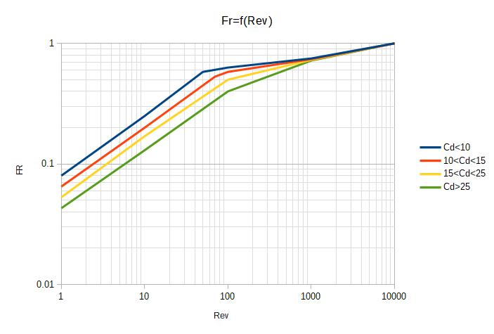
Blue curve : Cd<10, globe valves
Red curve : 10<Cd<15, globe valves and eccentric rotary plug
valves
Orange curve : 15<Cd<25, butterfly valves
Green curve : Cd>25, ball valves and very small valve with
Cd<1
STEP 6 : Calculation of Cv_corrected
Cv_corrected can thus be calculated thanks to Cv_turbulent / FR with Cv_turbulent calculated at Step 1 and FR calculated at step 2.
STEP 7 : Compare Cv_corrected to Cv_assumed [Valve Wolrd]
The Cv_corrected is compared the Cv assumed at step 2.
If Cv_corrected < Cv_assumed with Cv_corrected ~ 0.5*Cv_assumed, then the valve selected is fine for laminar flow.
If Cv_corrected > 0.8*Cv_assumed or even Cv_corrected > Cv_assumed, then the calculated must be repeated by selecting a valve with a higher Cv_assumed, advised to be 90% higher of the original value.
3. Calculation example
Considering a liquid of a viscosity of 1000 centistokes, with a density 0.9, what is the valve Cv required to ensure a pressure drop of 25 Psig for a flow of 30 gpm ?
STEP 1 : calculate the Cv turbulent
Cv_turbulent = q.(d/DP)0.5 = 30*(0.9/25)0.5 = 5.7
STEP 2 : select a valve
The Engineer wishes to use a globe valve of inlet diameter 1 inch. He anticipates a higher Cv required 90% higher than Cv turbulent, which means a Cv of 10.8.
Looking in a catalogue for Globe valve, the Engineer finds a model with a Cv of 12. The Engineer selects this valve. FL = 0.95 according to the manufacturer.

The coefficient Fd is 0.46 according to paragraph 2.
STEP 3 : calculate the Reynolds number of the valve
Rev = (17000*Fd*q)/(ν.[CvR*FL]0.5) = (17000*0.46*30)/(1000*(12*1)0.5) = 67.7
STEP 4 : Calculation of Cv/d2
STEP 5 : Calculation of FR
FR is calculated from the Abacus given in section 2 step 5. In the present case, it is 1st necessary to calculate Cd=Cv/d2 = 12 then check the 2nd curve on the graph for Rev=67.7
FR = 0.52
STEP 6 : calculate the Cv for laminar flow
Cv_corrected = Cv_turbulent / FR = 5.7/0.52 = 10.96
STEP 7 : control the value calculated
The Cv corrected is equal to 10.96 while the valve selected has a Cv of 12. 10.96/12 = 0.91.
The valve would regulate at 91% of its maximum Cv. It is too high,
it could be advised to re-run the calculation by selecting a
slightly bigger valve, for example with a Cv of 20.

control valves for non-turbulent flow (laminar and transitional)