
Rotary Airlock Valve : Engineering Guide
What is a Rotary Valve, Valve / Feeder / Star valve ?
Design, operation and troubleshooting of rotary airlock valves
Question or remark ? Please contact us at admin@powderprocess.net
| Section summary |
|---|
| 1. Introduction |
| 2. Drop Through / Blow Through |
| 3. Star valve clearance and contact detection |
| 4. Airlock explosion resistant and flame proof |
| 5. Star valve degassing |
| 6. Sizing tips & Interactive Calculator |
| 7. Troubleshooting |
| 8. Airlock rotary valve buying guide - How to select an airlock rotary valve |
An airlock rotary valve is a mechanical conveying device that allows to control a bulk solids flow (powder, pellets, granules...). Such airlock feeders (also called rotary valve feeder or star valve) are often used prior to a pneumatic transport system. Learn more all details rotary valves in this webpage.
Other pages of interest : Pneumatic transports ; Dosing and feeders ; Mixing and mixers ; Screw Conveyors
1. What is an airlock rotary valve
Airlock rotary valves are used at solids handling processes interfaces, typically when it is necessary to separate 2 areas under different conditions (pressure most of the time) while letting the solid go from one condition to another.
Rotary feeders are very widespread in process industries for bulk solids dry Mixing. Although other Mixers designs exist which are over-performing ribbon blenders in some areas (mixing speed, hygienic design...), rotary valves are still a very simple and robust solution to mix dry materials offering decent mixing performances which are sufficient for many applications.
Top 5 Most Popular
1. Pneumatic transport design guide
2. Ribbon blenders
3. Powder mixing
4. Hoppers design guide
5. Measuring degree of mixing
Top 5 New
1. Continuous Dry Mixing
2. Mixing speed
3. Mixer cycle time optimization
4. Batch / continuous mixing comparison
5. Energy Savings
Compared to other dosing equipment, rotary feeders have the following advantage :
Table 1 : Rotary airlocks vs other dosing equipment
| Advantages | Drawbacks |
|---|---|
| Continuous operation Simple (but rough) throughput adjustment if motor on VFD Low space requirements Some design with easy access for cleaning |
Feed pulsation (discrete discharge of pockets) Air leakage Chopping of large particles / pellets Can be damaged by abrasive products Limited operative pressure Delicate maintenance - needs well trained staff Can lead to Foreign Bodies incidents if not assembled properly |
2 types of airlock rotary valves are available : a drop through type and a blow through type. Both types are basically giving the same results, however, the way they do it and their characteristics are slightly different.
Airlock feeders are used widely in the industry with applications in the following areas :
- Food industries (baking, dairy, coffee, grains)
- Construction (cements, asphalt)
- Pharmaceuticals
- Mining
- Energy (power plants)
- Chemicals / Petrochemicals / Polymers
2. How does a rotary valve work ? Drop Through rotary valve and Blow Through rotary valve
Drop Through airlock rotary valve
Drop through airlock rotary valves are "dropping" the product to the pipe or equipment below. There is an entry flange and an outlet flange.

Figure 1 : Front view of a drop through star valve
Blow through airlock rotary valve
Blow through star valves are directly connected to a conveying line. The air used in the conveying line is therefore directly going through the alveoles of the valves, sweeping the product away.
Typically, blow through valves are used either when there is a very limited height or when the product has a tendency to stick inside the rotor. For other applications, the drop through model is quite preferred.
Having the rotor directly in the pipe flow can lead to larger breakage of the product being transported, it is especially the case if several drop through valves are in series in a same piping. For this particular case, drop-through valves may be considered in order to preserve the product.
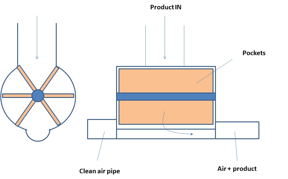
Figure 2 : Front view and side view of a blow through star valve
3. Airlock rotary valves mechanical design
3.1 Star Valve Clearance and Contact detection
Star valves have typically very small clearance in between the rotor blades and the stator, it is necessary in order to provide an air sealing in between upstream and downstream areas that are not at the same pressure.
Typical clearance for airlock rotary valves is \(0.1\text{ mm}\) and usually ranges from \(0.05\text{ mm}\) to \(0.25\text{ mm}\) depending on the service expected for the valve (high difference of pressure from each side of the valve or not). This is a very small clearance which explains that rotary valves often suffer of scratches due to contact rotor / stator. The following table is summarizing common causes of contacts.
Table 2 : Troubleshooting - Main causes of scratches for star valves
| Main causes of scratches for rotary valves | How to avoid |
|---|---|
| Incorrect dismantling / reassembly | Training of operator / mechanics Use of designs with extraction bars |
| Foreign body trapped in between rotor and stator | Install sieve and magnet in upstream process |
| Thermal expansion reducing clearance | Proper specification of the valve and design of process (after cooler, temperature sensor) |
Scratches can have different consequences : blockage of the valve, reduction in air sealing, foreign bodies generation. It may be necessary to repolish the valve after a scratch, which has as a consequence to extend locally the clearance and reduce the sealing capacity of the valve.
To be noted that some designs have been developed where the blades have an adjustable tip bolted. If the tip is made of soft material like Nylon, it allows to touch the stator without damage. It is however subjected to wear and has a limited range of applications.
3.2 Blade Forms
The design of blades within airlock rotary valves plays a crucial role in their functionality and efficiency. Blade forms and tolerances directly impact material flow, sealing, and overall performance.
- Standard Blades: These blades are typically used for free-flowing granules or powders. Their design allows for efficient material transfer while maintaining a secure seal.
- Scoop Blades: Scoop-shaped blades are ideal for handling cohesive or sticky materials. Their design aids in breaking up clumps and ensuring consistent material flow.
- Beveled Blades: Beveled blades are employed when precise metering and dosing are required. They allow for controlled material discharge, making them suitable for batching applications.
3.3 Balancing Blade Forms and Tolerances
- Material Compatibility: Tailor blade forms and tolerances to match the specific flow characteristics and adhesion properties of the material being handled.
- Valve Type: Different valve types (e.g., drop-through or blow-through) may require adjustments in blade forms and tolerances to ensure efficient operation.
- Maintenance Requirements: Regular inspection and adjustment of tolerances may be necessary to maintain sealing integrity and prevent wear over time.
- Consultation with Experts: Seek guidance from rotary valve manufacturers or experts in material handling to determine the most suitable blade forms and tolerances for your application.
3.4 Material Options: Stainless Steel vs. Carbon Steel
Stainless steel is renowned for its durability and corrosion resistance properties. This material is an excellent choice for airlock rotary valves in industries where hygiene and material purity are paramount, such as food processing and pharmaceuticals.
- Corrosion Resistance: Stainless steel's resistance to rust and corrosion ensures a longer lifespan, even in challenging environments.
- Hygienic Properties: It is easy to clean and maintain, making it ideal for applications that demand strict cleanliness standards.
- Product Compatibility: Stainless steel is compatible with a wide range of materials, preventing contamination and ensuring product integrity.
Carbon steel, on the other hand, offers robust strength and cost-efficiency. It is commonly used in industries where corrosion resistance is not the primary concern:
- Strength: Carbon steel's strength and toughness make it suitable for handling heavy materials and enduring rugged conditions.
- Cost-Effective: It is often a more budget-friendly option compared to stainless steel.
- Versatility: Carbon steel can handle a broad spectrum of materials, making it suitable for industries like mining and construction.
3.5 Mechanical Sealing and Packing Seals
Airlock rotary valves rely on effective sealing mechanisms to maintain airtightness and prevent leaks. Two primary sealing methods are employed: mechanical seals and packing seals.
- Mechanical Seals: Provide precision, airtightness, and durability with reduced maintenance.
- Packing Seals: Use graphite or PTFE rope packing; cost-effective upfront and adaptable to irregular shafts, but require frequent maintenance.
4. Explosion protection
A rotary airlock can be used as an isolation element to prevent dust explosion from propagating in an installation. For this, the airlock rotary valve must be certified to be explosion shock resistant and flame proof.
In order to get those characteristics, the valve must be designed so that :
- The body and rotor can withstand the pressure of an explosion - typically \(10\text{ bar g}\).
- The clearance tip of the blades / housing must be less than \(0.2\text{ mm}\).
- At least 2 blades on each side of the valve must be in contact with the housing (which means total number of blades must be \(\ge 8\)).
5. Rotary Valve Degassing
A low clearance will allow a good sealing and reduce the rotary airlock valve leakage. However, even reduced, leakage will happen. As well, the air trapped in each pocket will be released when the pocket is opened to the low-pressure area.
The air leakage increases with the difference of pressure and increases with the rotation speed of the valve. It can be very detrimental to performance, especially with light powder, since released air fluidizes incoming powder and prevents pocket filling.
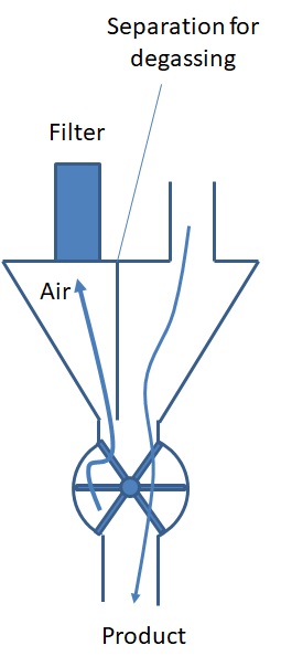
Figure 3 : Star valve equipped with degassing hopper feeding a pneumatic conveyor
6. Airlock rotary valve design calculations (sizing)
The capacity calculation of a star valve to achieve a given throughput is a function of the star valve diameter, its target rotation speed, and the powder characteristics:

Figure 4 : Typical capacity graph of airlock rotary valve
Capacity Equation:
\[ \dot{m} = V_{pocket} \cdot n_{pocket} \cdot N \cdot \rho \cdot \eta \cdot 60 \]

Equation 1 : Airlock Rotary Valve capacity calculation
Where:
\(\dot{m}\) = capacity in \(\text{kg/h}\)
\(V_{pocket}\) = volume of one pocket in liters (\(\text{L}\))
\(n_{pocket}\) = number of pockets (vanes)
\(N\) = rotation speed in \(\text{RPM}\)
\(\rho\) = bulk powder density in \(\text{kg/L}\) (\(\text{kg/dm}^3\))
\(\eta\) = filling rate / pocket filling efficiency (typically \(0.50 - 0.85\))
💡 Rules of Thumb for Rotary Airlock Sizing & Operation
- Typical Rotation Speed: Target \(15 - 25\text{ RPM}\) for standard powders. Speeds above \(30\text{ RPM}\) drastically reduce filling efficiency \(\eta\) due to short pocket dwelling time and blowback air turbulence.
- Rotor Tip Speed Limit: Must be kept \(< 1.0\text{ m/s}\) (\(\approx 200\text{ ft/min}\)) to minimize particle attrition and satisfy ATEX ignition safety requirements.
- Rotor/Stator Clearance: Maintain \(0.05 - 0.15\text{ mm}\) (\(0.002 - 0.006\text{ in}\)). Clearances exceeding \(0.20\text{ mm}\) lead to excessive gas leakage and loss of explosion flameproof barrier.
- Explosion Isolation (ATEX/NFPA): Minimum 8 rotor vanes required, with at least 2 vanes per side in contact with the housing bore at all times.
- Degassing Venting: Mandatory when feeding into pressure lines above \(0.2\text{ bar}\) (\(3\text{ psi}\)) or handling fine powders (\(d_{50} < 100\,\mu\text{m}\)).
⚡ Interactive Rotary Airlock Valve Sizer
Engineering Tool for Capacity, RPM & Tip Speed Calculations1. Sizing Parameters
2. Calculated Performance
7. Common problems with airlock rotary valves
Different problems can affect a star valve during its operation. Common problems are among the following :
- Performance below design (lower throughput than expected)
- Damage by metal / metal contact
- Wear
Table 3 : Troubleshooting - Main operational problems with airlock rotary valves
| Observation | Possible root cause | Possible action |
|---|---|---|
| Performance below design | The pockets are not completely filled The product has a bad flowability and the hopper above the star valve is not designed properly. The product is blocked before reaching the valve. |
This could be addressed by using discharging aids in the hopper. |
| Performance below design | The pockets are not completely filled In case of a valve used to feed a pressure conveying line, the air leakage is fluidizing the product at the star valve inlet, preventing it to fill its pockets : it could be due to an improperly specified valve with too large clearance, not enough vanes or a worn valve whose clearance are above specification. Another possible root cause is an improper degassing of the empty pockets before they reach the hopper to pick up again powder. Lastly, another possibility to be looked at is the air seal flushing : if it is set with a too high pressure, the air, leaking via the seal can oppose the flow. |
Check the specification of the valve regarding the pressure drop it has to overcome Review the degassing of the valve and the hopper above (if existing) Check the pressure of the compressed air sealing Note : Airlock rotary valves can be designed with 6-8-10 vanes. The more the number of blades, the tighter will be the valve. However, a high number of vanes will also reduce the volumetric capacity of the valve : an optimum is to be found in between sealing and pocket capacity. |
| Performance below design | The pockets cannot be emptied properly A bad discharge of the pocket is linked to the flowability of the powder. If the powder is very cohesive, it can actually stay in the pockets of the airlock rotary valve, which reduces the volume available for new product at each rotation. |
Some rotor design are existing with the bottom of pockets plain. Powder cannot accumulate there and falls easier from the pocket. |
| Damage by metal / metal contact | "Scratching" a star valve corresponds to a punctual metal / metal contact that will lead to a damage of the rotor and the stator. After such incident, the valve may be blocked, which prevents its use. During the incident, metal shavings can be released to the product stream which can be a problem for certain product applications. |
To prevent such damage, it is necessary to : - Make sure no foreign body can reach the valve (use sieves and magnets prior to the valve) - Make sure the valve is specified properly, especially the operating temperature since higher temperature can cause metal expansion and lead the valve to touching - Train people to maintain the valve since most of the equipment damages are linked to rotors improperly put back in the valve after maintenance - Use rotor / stator contact detection system In case of damage, it is necessary to remachine the valve, or change it entirely if clearances are too high after machining. |
| Wear [IAC] | Rotary valve wear corresponds to medium / long term damage of the valve. 2 main phenomena can lead to rotary valve abrasion : - Material is trapped in between a vane tip and the housing during rotation - Air leakage carrying at high speed particles of product which are eroding the valve It can be possible to estimate which phenomena is damaging a particular valve : if the housing is damaged on the loaded side (pockets full of product), the 1st phenomena may be at cause ; if the housing is damaged on the other side (empty pockets), the 2nd phenomena may be at cause. |
The following actions can be taken to prevent airlock rotary valves wear : - Select the right clearance to reduce chances of trapping product in between rotor and stator. It also reduces the air leakage responsible of erosion. - Use vane tip chamfered to reduce the potential contact surface with product trapped during rotation - Use a closed rotor (the sides of the rotor are closed which is limiting the leakage and avoiding friction - but not all application can accept it) |
8. Airlock rotary valve buying guide - How to select an airlock rotary valve
Airlock rotary valve for sale : Buying a new airlock rotary valve
When sourcing a new airlock rotary valve for your factory, the following questions need to be asked in order to buy the right specifications :
- Is the airlock rotary valve design better as blow through or drop through ?
- Do you need a special material (for instance stainless steel) or standard execution is sufficient ?
- What is the throughput you need and what is the bulk density of the material to process, it will give the diameter of the valve
- Is the valve submitted to heat ? Does it need to have specific rotor stator clearance ?
- Is the valve feeding to a pressure pneumatic conveying line ? Does it need degassing ?
- Is there a need of frequent access for cleaning inside the valve ?
- Is the powder free flowing or specific blades and pocket design is required ?
- Does the airlock rotary valve need to be certified for processing in a dust explosion area ? If yes, which zone classification is to be considered in and around the valve ?
- Does the valve need to be resistant to explosion (typically 10 bar) ?
Answering in advance to those questions will allow you to quickly specify the valve you need and engage a constructive discussion with an airlock rotary valve supplier.
Some references of airlock rotary valves manufacturers is given below :
- Sautelma Rotolok
- Young Massa
- Olocco
Note that PowderProcess.net has no link with those companies.
Frequently Asked Questions (FAQ)
How is the capacity of an airlock rotary valve calculated?
The mass capacity of an airlock rotary valve is calculated by multiplying the total rotor swept volume per hour by the loose bulk density of your material and a pocket-filling efficiency factor. The mathematical formula is expressed as: \(\dot{m} = V_{pocket} \cdot n_{pocket} \cdot N \cdot \rho \cdot \eta \cdot 60\), where \(V_{pocket}\) is individual pocket volume, \(n_{pocket}\) is number of vanes, \(N\) is shaft speed in RPM, \(\rho\) is bulk density, and \(\eta\) is filling efficiency.
Why does rotary valve capacity level off or drop at high speeds?
At high rotation speeds (typically above 30 to 35 RPM), the time that each rotor pocket spends exposed to the inlet feed decreases, preventing complete gravity filling. Furthermore, on pressurized conveying lines, high-pressure air trapped in returning empty pockets expands into the inlet zone, fluidizing incoming powder and restricting solids intake.
What is the difference between drop-through and blow-through rotary valves?
A drop-through rotary valve drops material by gravity into an inline hopper or pipe below, whereas a blow-through valve features a direct line connection where high-velocity conveying air passes through the pocket spaces. Blow-through designs are preferred for sticky materials, while drop-through designs are preferred for fragile or abrasive powders.
[IAC] : Everything you need to know about rotary airlock valves, Bob Mace, IAC