Continuous dry mixing
Continuous powder mixing / Continuous powder blending
Question or remark ? Please contact us at admin@powderprocess.net| Section summary |
|---|
| 1. Introduction |
| 2. Principle of
continuous dry-mixing |
| 3. Mixers for continuous dry-mixing |
| 4. Feeding in continuous dry-mixing |
| 5. Control of continuous dry-mix
systems |
| 6. Continuous dry-mixing application |
1. Introduction
When thinking about dry-mixing, the 1st processes that usually come to mind are batch processes with the mixture done very often with simple configurations. However, it is also possible to design a continuous mixing process. Such a process differs in many aspects from its batch competitor and requires a very careful design but it can bring decisive advantages in terms of compactness, stability and capacity.
2. Principle of continuous mixing
What is continuous powder mixing ?
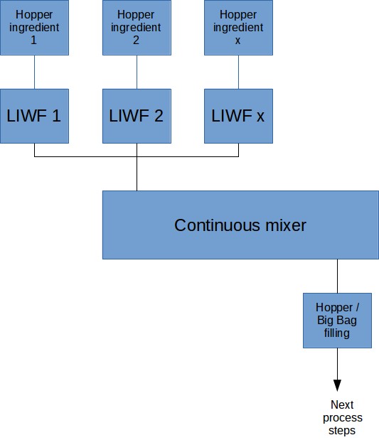
In continuous dry mixing, the different solid components making the mix must be fed continuously to the mixer and an equal amount of mixture must be removed continuously on the other side.

Figure 1 : Block diagram of a continuous dry-mixing process
Top
5 Most Popular
1.
Pneumatic transport design guide
2. Ribbon
blenders
3. Powder mixing
4. Hoppers design guide
5. Measuring degree of
mixing
-----------
Top 5 New
1.
Continuous Dry Mixing
2. Mixing speed
3. Mixer cycle time optimization
4. Batch / continuous mixing
comparison
5. Energy Savings
As many components as necessary can be fed to the mixer by loss in weight feeders, up to the limit of the space available in the layout. The mixer is using a plug flow principle but should however allow a certain degree of back mix in order to cope with dosing inaccuracies of the Loss In Weight Feeders (LIWF). There are indeed 2 mixing effects that need to be combined in order to reach a proper degree of homogeneity : radial mixing and axial mixing.
- Radial mixing : the mixing happens radially, we can imagine that the mixer is divided in small cells inside which the mixing is happening. The product is moved from on cell to another until the end side of the mixer.
- Axial mixing : a perfect plug flow inside the continuous mixer, with only radial mixing is not advisable. Indeed, contrary to a batch mixer, one important source of variability is the slight changes of flowrate from the loss in weight feeders. It can happen that a feeder delivers temporarily more or less flow vs the setpoint, if only radial mixing is happening, some mixing cells may stay with significantly lower or higher quantity of a particular component, leading to a very strong CV. A degree of axial mixing, or back mixing, will allow to transfer part of the mixture from one cell to another and smoothen the variability due to the dosing, leading to a higher degree of mixing.
3. Mixers for continuous mixing
Which mixer can be used for continuous mixing ?
The following designs can be found in the industry to perform continuous mixing :| Mixer type |
|
| Ribbon blenders (these are usually old designs less in application today) | Those mixers operate at Fr < 1. The ribbon design is able to move the material in different directions so that a mixing effect is achieved. Some manufacturers propose to have a mixing tool made of 2 helix rotating at different speed to have a better mixing. |
| Single shaft paddle mixers | Operate at higher Froude and allow a shorter mixing time than ribbon based mixers. A fluidization is achieved in the mixer. The level in the mixer can easily be adjusted thanks to an overflow plate at the end of the mixer |
| Double shaft paddle mixer | Operate at Fr = 1.1 with a fluidized zone in between the 2 mixing shafts. The design is similar to batch paddle mixers but they are equipped with a plate at the end of the mixing area allowing to define the level of product in the mixer and thus the residence time. |
| Ploughshare mixer | The design is smilar to the batch mixers but have a specific outlet to continuously remove product |
Note : The links above lead to pages related to the batch version of the mixers, although the design and mixing principle is finally very close to the continuous versions.
3.1 Residence time
The residence time in continuous mixing is typically very short, due to the size of the machine and the mixing principles used by the mixer. Typical residence times are in the order of magnitude of 10 s to 1 min, varying with the mixing technology and type of the mixture.3.2 Capacity
The hold up volume of continuous mixer is usually very low compared to the equivalent in batch required to get the same capacity in t/h. The design capacity can be sized from few liters per hour in pharma (10 l/h) to several thousands l/h in chemicals or food processing (800000 l/h).
It should be noted however that continuous systems, once they have been sized and installed are not very flexible and should be operated close to their design throughput.
3.3 Settings
Continuous dry mix lines can be operated following mainly 2 process levers : the mixer speed and the residence time
| Lever | Effect |
| Mixing speed | The agitator speed will define the mixing intensity and will have an effect on homogeneity but also impact on the product (breakage) |
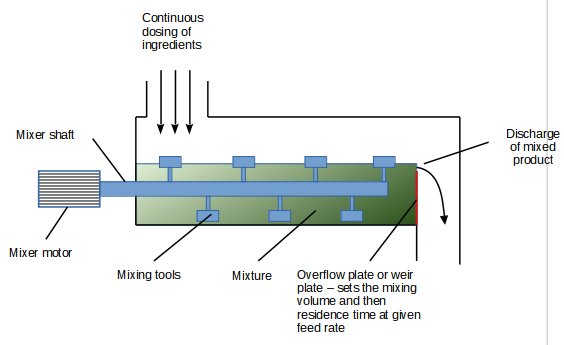
| Residence time | The residence time is adjusted in most mixer thanks to a
plate at the end of the mixer which is defining the level of
product in the mixer and therefore the residence time
depending on the feed rate. A short residence time will give less time for mixing and will lead to a higher CV. Optimizing the residence time will allow to get the highest capacity for the best mixing efficiency and the less impact on the product. |

- Figure 2 : Continuous mixer for dry powders and adjustment of residence time
-
4. Feeding in continuous dry-mixing
How to continuously dose powder ?
Continuous loss in weight feeders must be used for dosing the powder towards a continuous dry-mix. The design and installation of those feeders is of critical importance for the stability of the process and the quality of the mixture obtained. Indeed, the feeder's load cells should not be disturbed by any of the equipment around, the flow inside the feeder must be regular and the refilling must happen swiftly to reduce the time the system is running in volumetric flow.
4.1 LIWF installation
Loss in weight feeders must be installed on a stable structure, i.e. a slab or a strong steel structure, which is not transmitting vibrations that could be generated elsewhere in the plant. Special flexibles should be used before and after the feeder to allow for a free movement of the feeder and thus accurate weight measurement by the load cells. All cables connected to the feeder must be installed in a way that they are loose enough not to create any tension - push or pull - on the feeder.
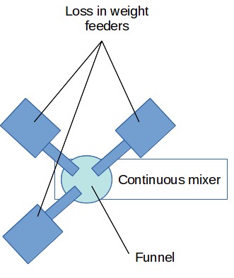
When many feeders have to be used, a funnel positioned above the mixer can be installed in order to collect the powder from the different feeder and direct them to the inlet of the mixer. If 2-4 feeders only are used, they can feed directly to the mixer through different inlet ports at the beginning of the mixer.

Figure 3 : Typical feeder arrangement for a continuous dry-mix - top view
The mixer must be very well vented in order to avoid any back
pressure to the feeder. Even if mechanical or electronic pressure
compensators exist, it is always preferable to avoid pressure
effects in the system.
4.2 LIWF refilling
A system to refill the feeder must be designed and installed. As the feeders are controlling their speed thanks to the loss of weight over time, such control is not possible anymore when powder is loaded to the mixer as the weight increases. The feeder then switches to a volumetric, fixed speed, feeding which is far less accurate than gravimetric feeding. In order to keep a good average accuracy over time it is thus critical that the refill be done very quickly. 30 s for a refill appears in most of the cases a maximum, and refills should not be too often so that the feeder can dose in gravimetric mode for 85-90% of the time.
In order to have such a fast refilling, a hopper must be positioned above the feeder, with a short drop tube, and most of the case only a butterfly valve to start and stop the discharge. The hopper must be designed to allow a very good flow so that there is no waiting time in between the demand of refill and the actual flow of product. If it is not possible to design the hopper so that bridging or ratholing are avoided, discharging aids must be installed.
The venting of the feeder is critical to make sure that the refill will be quick, and that no pressure build-up will have to be vented while the feeder has switched back to loss in weight, which would disturb the load cells and create inaccuracies in the flow.
4.3 LIWF control
Loss in weight feeders are controlling the speed of the dosing
equipment (very often a screw) by measuring the loss of weight over
time and comparing it to the set point. Algorithms have been
developed by manufacturers in order to filter possible disturbance
on the load cells that usually happen in an industrial environment.
Those filters are however efficient only on small disturbances thus
it remains important to follow the good practices in installing
feeders. When detecting a big variation, the feeder will switch to
volumetric mode in an attempt to keep a reasonable dosing accuracy,
but the disturbance has to be very short for this method to be
effective.
5. Control of continuous dry-mix process
How to control a dry-mixing process ?
Contrary to a batch process, a continuous mixer will experience transient regimes at start-up or any time a process parameter is changed. The control system must be able to manage those transition phases and possibly divert the mixture for rework at start up when the mix is not yet optimal.
It is critical to monitor the loss in weight feeder and define some acceptable limits in their flowrate variation. If one of the loss in weight feeder cannot keep its setpoint for a certain time, the system should alarm and possibly stop the dry-mix line. Those acceptable level should be calculated based on the required composition of the mix or defined through experience.
Extruder analogy
Note that the process for continuous dry-mix is somewhat very similar to the use of extruders : it is necessary to dose and control the flow of the materials to the extruder, the extruder is mixing the components and has more or less back mix according to the profile which is used on the shaft, and the product is continuously discharged at the end of the extruder.
6. Continuous dry-mixing application
Continuous dry-mixing of powders has a wide range of applications across a variety of industries. Continuous mixing for food and pharmaceuticals has gained some popularity over the years. In the food industry, continuous mixing is used for the production of snack foods, baked goods, and powdered drink mixes. In the pharmaceutical industry, continuous mixing can be used to produce medications, as well as to blend active pharmaceutical ingredients with excipients. Small continuous mixing lines for pharmaceuticals can offer advantages in terms of batches validation which is tightly controlled in pharma. Other industries that rely on continuous dry-mixing include chemical manufacturing, ceramics, and construction materials.