Pneumatic Conveying Systems introduction
For full information on pneumatic transport, you can look further
in our pneumatic
conveying handbook
Question or remark ? Please contact us at admin@powderprocess.net
| Section summary |
|---|
| 1. Types of pneumatic transport : Dilute Phase / Dense Phase |
| 2. Process |
| 3. Design - Shortcut calculation method |
| 4. Troubleshooting |
| 5. Suppliers of pneumatic conveying
systems |
What it is about
Along a production process, powders need to be transported. Pneumatic conveying systems are often an efficient way to move powders compared to other mechanical means (use of bags or containers, use of belts...)
There are however different ways to perform a pneumatic transport, such as pressure air transport or vacuum transfer system for powder. Each way has some advantage and drawbacks, thus the choice of the technology must be done after carrying out a short study. This study must consider the process needs but also the influence of the pneumatic transport on the products.
This page is proposing an overview of pneumatic conveying technology, however powderprocess.net has also crafted an online handbook with more details, please click on this link to reach it.
1. Types of pneumatic conveyors
What is pneumatic transport ?
In each case, pneumatic transport will involve a gas as a powder mover. This gas is blown on one side of the process and the mixture gas + powder flows in conveying pipes until the its final destination. In most of the cases, the gas used is air. There are however different ways to blow the air, introduce the powder in the conveying pipe. As a consequence different transport technologies have been developed over time.
What type of pneumatic conveying systems are typically used ?
Lean / Dilute phase
A very common way to transport powder is to transport it in a dilute phase. The powder is diluted by the air which means that the ratio (kg product/kg air) is low. The product is transported in the form of a cloud in the conveying pipes.
PRESSURE lean phase
The air in the conveying pipe can be introduced thanks to a Blower, with an overpressure at the beginning of the conveying pipe. We will then talk about PRESSURE lean phase
VACUUM lean phase
Instead of placing the Blower at the beginning of the conveying pipe, it can be placed at the end. In this case, the Blower is creating a VACUUM that will suck air in the conveying pipe. This air will drag the powder and transport it to the final receiver.
Top
5 Most Popular
1.
Pneumatic transport design guide
2. Ribbon blenders
3. Powder mixing
4. Hoppers design guide
5. Measuring degree of
mixing
--------
Top 5 New
1. Continuous Dry Mixing
2. Mixing speed
3. Mixer cycle time
optimization
4. Batch
/ continuous mixing comparison
5. Energy Savings
Dense phase
The other option, to transport powder, is to transport at a much higher concentration the product. A transport is called dense phase when the ratio (kg product/kg air) is high. Again, such transport can be carried out in pressure or in vacuum.
PRESSURE dense phase
In pressure dense phase, air must be compressed at higher pressure than in lean phase. It can be done by installing a specific compressor, or simply by using air from the compressed air network of the factory. Pressures reached will range from around 1 bar g to several bag g. To introduce the powder in the transport pipe, some tanks, designed to withstand pressure, are often used. They are called pressure tank or pressure sender hoppers.
VACUUM dense phase
Vacuum dense phase will present a quite similar setup than the lean phase one. However, in order to accommodate higher solids loads, leading to higher pressure drop, a vacuum pump will be used instead of a simple roots Blower. Very high vacuum will then be generated.
Summary table
Table 1 : Pros and Cons of the different pneumatic conveying technologies
| Phase | Driving force | Solids load | Pressure | Achievable distance | Pros | Cons |
|---|---|---|---|---|---|---|
| Dilute | Pressure | 5-15 | Max 800 mbarg | 150-200 m or more | Simple Instictive and easily understood by operators |
Requires star
valve at product pick-up Air may be hot after compression |
| Dilute | Vacuum | 5-15 | Max -500 mbarg | 100 m | Simple Product pick-up is simplified (no need of star valve) Air is sucked at the environment temperature |
Limited in distance compared to conveying in pressure The operation can appear more delicate to production operators |
| Dense | Pressure | 25-30 | From 1 bar g to several bag g | Can be 150+ m, but other factors may limit the distance | High distance can be reached High product flow can be reached |
Compressed air consumption Use of pressure tank Difficult access to the inside of the pressure tank |
| Dense | Vacuum | 25-30 | Up to -900 mbar | ~50-100 m | No consumption of compressed air Simple product pick-up, easy access to sender hopper |
Limited in distance and elevation |
Dense phase - Some variations
When conveying in dense phase, suppliers may use different technologies inducing a different behavior of the powder in the conveying pipe. In the simplest configuration, plugs of different length will naturally be created. This may cause some issues regarding the pressure drop as there may only be one single long plug. To decrease this phenomena, there are possibilities to force the creation of shorter plugs. It is done by pulsing a valve admitting air at the beginning of the conveying pipe or at intermediary sections. One drawback is that the air introduced in the conveying pipe will cause an acceleration of the product conveyed at the end of the line, which may be detrimental to the product quality (breakage).
Flow regimes
Be careful, not all the solids can be transported with any technology. Actually, the adequacy of a particular technology will depend on the fluidization properties of the solid to be transported. Before designing a system, the class of the solid must be established. Such class is determined thanks to a classification proposed by Geldart in 1973.
- Class A : powders adapted to dense phase conveying, they have a very high and lasting aeration. They can be transported at high concentration but do not form naturally some plugs, an active system is therefore require to create them.
- Class B : powders adapted to dense phase conveying, will naturally flow in plugs (dune)
- Class C : these cohesive powders are probably not transportable in dense phase, however some exceptions exist
- Class D : these powders can be transported in dense phase at concentration in between class B and class A

Figure 1 : Geldart classification
The density ρp of the particles used on the graph above is defined as the mass of a particle divided by its volume, including open and closed pores.
It is important to understand how the concepts of lean phase and dense phase translate on the way the product is flowing in the pipe. Basically, depending on the velocity of the transporting gas, 5 flow regimes can be identified.
Table 2 : Conveying phases
| Gas speed | Flow regime | Conveying pipe Aspect | Comments |
|---|---|---|---|
| High speed (15-40 m/s) | Dilute Phase |  |
Basically, any solid can be transported in dilute phase,
however the constraints applied to the solid make it
suitable only for product which are not sensitive to
breakage and which are not too hard and abrasive for the
piping. Particles are in suspension in the gas and are not depositing on the transport pipes. |
| Medium speed (8-15 m/s) | Dense phase (saltating flow) |  |
When the gas velocity decreases, the pressure drop decreases to a minimum and some particles form a continuous layer in horizontal pipe sections. Deposits are not permanent and conveying is actually happening. The concentration is not constant over a pipe section since more particles are at the bottom of the pipe. |
| Low speed (3-8 m/s) | Dense phase discontinuous - Dune |  |
When decreasing further the gas velocity, the pressure drop increases again and a flow regimes where plugs are formed. The dune flow actually happens for fine products. The pressure drop will depend on the length of the plugs formed, thus the incentive to actively control them thanks to the process. One common method for this kind of flow regime is to install regular air injection in the pipe that will help to "cut" the plugs. |
| Low speed (3-8 m/s) | Dense phase discontinuous - Pulsating |  |
This flow regime is close to the dune flow presented above but is this time more happening with coarse materials. Observing the flow, it is clearly observed that it starts / stops, thus "pulsating". Plugs are created naturally thanks to the higher porosity of the solid compared to other more cohesive powders. |
| Very low speed (3-8 m/s) | Dense phase continuous |  |
Decreasing further the gas velocity, and for solids that are able to be conveyed under this regime, a continuous dense phase flow is established. Basically there is only one big plug. However, this creates very large pressure drops, which makes this regime limited to very short distances. |
It must be noted that the particles circulate at a lower speed than the gas. Depending on the flow regime, the particle average speed can be 0.4 to 0.8 times the gas velocity.
2. Constitution of each types of pneumatic conveying systems
PRESSURE - Lean Phase
The air mover in pressure lean phase is most of the cases a Blower or compressor. The most common type is to use a Roots Blower which combines good reliability, high air flow and can reach enough pressure for most of the industrial needs. This Blower will allow to reach max 1 bar g.
Another possibility is to use compressed air for some specific cases using a venturi to pick-up the powder. This solution is not very economical, therefore it should be kept for very specific cases and low throughput.
In order to introduce the powder to the conveying pipe, an Airlock rotary Valve should be used. This equipment will allow a rough dosing of the powder to the pipe, which is necessary to avoid blockages but will have as main function to isolate the area of high pressure (the pipe) to the area of low pressure (the hopper introducing the powder). This avoids to have the air going in the product and preventing its flow.
The receiver is most of the time equipped with an Airlock rotary Valve also in order to allow a separation of the air and the product. In some cases, it is possible to avoid such star valve if the receiver is big enough and the situation is safe (discharge directly to a silo).

Figure 2 : Pressure lean phase typical process arrangement
VACUUM - Lean Phase
In vacuum lean phase, the air mover is basically the same than in pressure lean phase, except that it is positioned at the end of the line thus sucking the air and creating a vacuum. The vacuum created is around -500 mbar g at compressor suction.
At product pick up, there is the need of having an air inlet to allow the air sucked to flow in the pipe. On the product side, no Airlock rotary Valve is necessary here since the air will go in the direction of the product and will therefore not prevent it to flow. A system to control the product intake is however necessary (screw, simple valve) in order to avoid that a surge in product flow block the pipe.
At reception, the best practice is to position a cyclone with an Airlock rotary Valve. The design must take into account that the air flow from the downstream equipment will this time flow against the product. A proper degassing must be considered.
Typical instrumentation should include the following : pressure sensor at compressor suction, differential pressure drop through filter, level sensor at reception

Figure 3 : Vacuum lean phase typical process arrangement
Vacuum transfer system for powder are getting popular for their simplicity at product pick-up and their enhanced containment as, in case of leak, air will leak towards the process, and the product will stay in the equipment.
PRESSURE - Dense Phase
Pressure dense phase will require a specifically designed sender hopper in order to withstand pressures from 1 to 3-4 barg in most cases. Such a tank is called a pressure tank. It features a compressed air inlet at the top and another one after its discharge valve. It should also be equipped with a pressure safety valve in order to avoid any uncontrolled pressure increase. A degassing system with a filter must also be installed.
The receiver must be equipped with a filter and may also be equipped with a star valve if necessary. If the receiver is big enough and designed to work at atmospheric pressure, such equipment may not even be necessary.
As part of the instrumentation, pressure sensors in the tank, at the beginning of the pipe and at reception will be key since the whole system will be driven depending on the pressures. Level sensors in the sender hopper in order to detect the end of filling and the end of discharge are necessary while a level sensor at the receiver should be installed to avoid overfilling. Compressed air flowmeters are optional but constitute a good troubleshooting tool.

Figure 4 : Pressure dense phase typical process arrangement
VACUUM - Dense Phase
A vacuum dense phase system is quite similar to a lean phase setup except that a vacuum pump allowing to reach pressure <-900 mbarg should be installed.
The inlet of material is usually done through a sender hopper. No specific construction for the sender hopper is needed, which can be an advantage compared to pressure dense phase since the access is easier.
The receiver, on the contrary, must be designed for full vacuum, which means it must be reinforced and will account for some cost increase. It should be equipped with a star valve or with a butterfly valve if the transport is in batch
A pressure sensor at the receiver and at the pump suction is necessary. The pump should be on frequency drive.

Figure 5 : Vacuum dense phase typical process arrangement
3. Design - shortcut method for Lean Phase pneumatic
conveying
The details of the method and examples are give in our pneumatic conveying handbook
STEP 1 - Collect the study entry data
The product to be conveyed needs to be known, especially :
- Mean particle size (microns)
- Bulk density (kg/m3)
- Particle density (kg/m3)
The pipeline geometry needs to be known :
- Length (m)
- Elevation (m)
- Number of bends
and angle
The target flowrate to achieve needs to be determined in advance (kg/h).
Some assumptions or design decisions needs to be done :
- Type of air mover / Pressure drop available
- Pressure at product pickup / receiver - Conveying capacity
targeted
STEP2 - Assume a pipeline diameter
Estimate the pipe diameter from experience. This is a starting point for the design procedure and the value will be checked and change later in the design if necessary.
STEP 3 - Assume a pressure drop for the line
Estimate from experience the pressure drop that should happen in the line. The value will be controlled and revised later in the procedure. Now, for a specific technology, this value should not change too much. For example, the pressure drop with a roots Blower should somehow be in the 0.3-0.7 bar.
STEP 4 - Calculate inlet air velocity
A common rule is to consider C1(velocity at pick-up)=1.2*Cmin (minimum air velocity). Cmin is either known, if the material is common or usual for the company running the product. If unknown, it is necessary to calculate it by checking the terminal velocity of a free falling particle, the min air speed must be greater than this value.
STEP 5 - Calculate the air mass flowrate
From the assumptions taken above, the air mass flowrate can be calculated thanks to the following formula :

STEP 6 - Calculate the solids loading ratio
The ratio is calculated from the target solids conveying rate and the air mass flowrate calculate above

With mp the product flowrate in t/h, ma the air conveying flowrate in kg/s
STEP 7 - Check conveying line inlet air velocity
This step only applies for materials being transferred in dense phase. For such material calculate C1=36Φ-0.3-7 m/s
If this approximate value is different to the one assessed in step 4, return to step 4 and replace the value
STEP 8 - Check conveying line pressure drop
Use a model to calculate the line pressure drop with all the data compiled at the previous steps. If the pressure drop calculated is different than the one evaluated in step 3, it is necessary to return to step 3 and replace the value.
Models
Such models are available for lean phase conveying. In case the system is being designed for dense phase, it is necessary to have empirical values from a test.
| Shortcut calculation method for dilute phase pneumatic conveying |
| Air only pressure drop method |
| Universal conveying characteristics method |
Details on such methods can be found in the litterature.
STEP 9 - (Only if the pressure drop calculated at STEP 8 was very far from the original guess) Re-specify material flowrate
If the calculated pressure drop is very far from the value assumed in STEP3, it may be necessary to correct also the product flowrate
STEP 10 - (Only if the 2 previous steps did not give satisfaction) Re-select pipeline bore
If the design is very far from the target, the pipeline bore should be changed and the calculation re-run until the input and output values for pressure drop are almost equal.
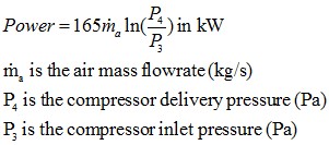
STEP 11 - Calculate the power required
For the purpose of this shortcut methode, the power can be calculated with the following estimation :
STEP 12 - System re-assessment
This step is added in order to allow the Engineer to have a critical eye on the data calculated so far and confront them to his experience. If necessary, some values should be modified and the procedure re-run.
SPECIFY the system
From the calculation done, specify the pipeline bore chosen as well as the air requirements.
4. Troubleshooting of pneumatic transport systems
The following phenomena can be observed when running a pneumatic transport line. For each issue, a common cause and action is given.
Table 3 : Conveying line operation troubleshooting
| Observation | Possible root cause | Possible action |
|---|---|---|
| High pressure during conveying | Too much product in the line | Review the settings of the equipment feeding the
material For dense phase, adjust the pressure in the pressure tank and action of discharge aids if any For vacuum dense phase, adjust air injection / plug forming valve |
| Not enough throughput | Line is under-designed | Review piping diameter and the Blower
sizing. Note : changing only the Blower may not be enough to increase the throughput Note : pressure drop is particularly high at bends, having a more direct piping layout will lead to less pressure drop and potentially more product throughput. |
| Not enough throughput | Note enough product admitted | Check the dosing equipment status. Especially for star valve, make sure that the venting is correct and that product can actuallz fill the pockets of the valve |
| Not enough throughput / pipe blockage | Piping leaks | Especially valid for vacuum system. Make sure, by performing a vacuum test, that the piping is tight. |
| Product build-up at bends | Too much / too sharp bends | Review piping diameter and the Blower
sizing. Note : changing only the Blower may not be enough to increase the throughput |
| Product build-up at bends | Too high air velocity | Review if air velocity can be decreased, be careful not to have too low speed at product pick-up, if the minimum pick-up velocity is not reached, a blockage at the start of the line could happend. |
| Product build-up in the piping | Condensation or product moisture pick-up | Review Review the air conditionning of the conveying air, make sure no humid air stream crosses a cold air stream or cold pipe section |
5. Manufacturers of pneumatic conveying systems
The selection of a supplier for your new pneumatic conveying system should be done very carefully to make sure the manufacturer selected have the proper knowledge and experience in your field of application. As part of the criteria to chose your supplier, should be their existing references but also if they have a pilot plant available to test your materials, as pneumatic conveying is very much material dependent. Additionally, the manufacturer should be able to give you precise and concise technical explanations during the discussion of your project.
The following companies are suppliers of pneumatic conveying systems (dilute phase conveying systems or dense phase conveying systems) :
- Sautelma : http://www.sautelma-rotolok.fr/
- Linxis group : https://linxisgroup.com/
- Lessine : https://www.lessine.com/
(Note that PowderProcess.net has no link with those companies)