Pneumatic Conveying Bends
Design, pressure drop, material attrition and wear, optimization in bends and elbows used in a pneumatic conveying line
For calculating pressure drop in conveying pipe, please visit our pneumatic conveying handbook
Question or remark ? Please contact us at admin@powderprocess.net| Section summary |
|---|
| 1. Introduction |
| 2. Bends design |
| 3. Bends effects |
| 4. Solving problems linked to bends |
1. Introduction
Bends in Pneumatic Conveying lines are necessary, it is indeed very seldom to have just a straight pipe in between the pick-up point and the receiving point. However, bends can be a source of issues not always well understood by the manufacturer.
Shortly after installing a new conveying line, the following observations may be done, if problem actually arise from bends in a conveying line :
- The line is choking (blockages)
- Pressure drop is too important, reducing capacity
- Conveyed materials are damaged
- Build-up happens in the line
Those issues may be avoided (experience shows that problems have sometimes several root causes) if the Conveying Pipe routing had been designed differently, with less or different bends.
2. Bend Design
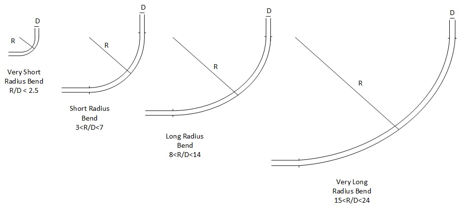
Bends can take several shape, from the sharpest (simple 90 degree tee) to long radius, or with more complicated and patented design. The table below gives an overview of each design available, with some remarks on design pros and cons.

Top
5 Most Popular
1.
Pneumatic transport design guide
2. Ribbon
blenders
3. Powder mixing
4. Hoppers design guide
5. Measuring degree of
mixing
Top 5 New
1. Continuous Dry Mixing
2. Mixing speed
3. Mixer cycle time
optimization
4. Batch
/ continuous mixing comparison
5. Energy Savings
Figure 1 : Regular bend designs
| Type of coupling | Ratio R/D | Remark |
|---|---|---|
| Very Short radius | R/D=1 to 2.5 | Also called elbow. Very sharp bend. High damage of conveying material expected if the material is fragile, high wear of the bend expected if the material is abrasive, high pressure drop |
| Short radius | R/D=3 to 7 |
Sharp bend. High damage of conveying material expected if the material is fragile, high wear of the bend expected if the material is abrasive, high pressure drop. To be used only if space constraints don't allow higher radius bends. |
| Long radius | R/D=8 to 14 |
Usually the best compromise in between space, impact on product, durability and pressure drop. It is however not always the case, as long radius bends are often thought to be able to solve all problems, but it is not true for all applications |
| Very Long radius | R/D=15 to 24 |
Very long radius bends may be perceived as a solution to reduce further breakage of conveyed material and wear but long radius may actually trigger other problems as the materials will bounce many times while in the bends, leading again to some breakage or material build-up in the pipe |
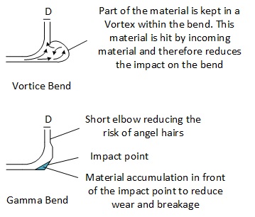
| Proprietary design | Usually very short or short radius | Some manufacturers propose more advanced bends allowing to avoid some of the drawbacks of regular bends. Most of these design are based on the formation of a pocket of material at the bend, which allows to absorb the impact from the incoming material and therefore reduces the solid attrition and the wear of the bend. Design try to minimize the effect of "dead area" that would make material stay very long time in the pocket by promoting a renewal of the material, but this is not guaranteed making those design quite appreciable in chemical applications but much less in food or pharma. |
Table 1 : Different types of piping connections and their advantages and drawbacks

Figure 2 : Proprietary bend designs
3. Bends effects
Bends have mainly the following process consequences :
- Pressure drop : when the flow of product is changing direction, the speed of the solids being conveyed drops after impact on the bend, additional energy is therefore required to re-accelerate the material, which translates in additional pressure drop.
- Pipe blockage : if the pressure drop at bend is too high, then product can settle, not being re-accelerated, and then trigger a pipe blockage
- Product damage : sending a solids at high speed in a bend will likely damage it, breaking the solid in smaller particles, or, for example with plastics pellets, wearing it
- Pipe damage : conversely, the impact of the product on the bend can create wear at the impact point on the bend, resulting to the need to replace it after several months or years.
4. Solving Problems linked to bends

Figure 3 : Product flow within a bend
Note : the drawing above is showing a flow pattern with several impact, but it may also happen, depending on the material and solids loading that the material slides on the outer part of the bend. This is what can happen in long radius bends with polymers for example and create smearing leading to angel hair when the layer of product accumulated peals off.
| Problem | Possible action(s) |
|---|---|
| Line blockages at bends | 1. Don't position a bend just after the pick-up point of the
conveying line, always respect 2-3 m straight line, up to 6 m
when using long radius bends 2. Use shorter radius bends as less product will settle in the bends, it may reduce the risk of blockage 3. Don't use consecutive bends, always respect a straight distance in between bends |
| High pressure drop | 1. Reducing the number of bends in the pipe layout : one
should always plan for the straightest pipe as possible,
better to have a longer piping than many bends 2. Opt for long radius bends that will reduce the pressure drop versus short radius ones |
| Breakage of solids conveyed | 1. Reducing the number of bends in the pipe layout : one
should always plan for the straightest pipe as possible,
better to have a longer piping than many bends 2. Use longer radius bends, although it may not be the best choice for all solids as the longer the bend radius, the longer the solids will be dragged against the bend and ricochet many times. Plastic pellets for examples will slightly melt when being dragged and deposit a layer of product in the bend, when this layer peals off with time, it creates the well known phenomena of "angle hairs" which can be perceived by customers as a quality defect. Regarding "angel hairs", it may be better to use simple short radius bends or short radius bends with specific designs creating a cushion of product at the impact point (Gamma Bend) 3. Use pressure conveying instead of vacuum conveying as the end of line velocity is lower, also arrange layout so that bends are not located at the end of the pipe, where the velocity is the highest 4. Change the conveying technology : dense phase, with air velocity around 5 m/s will create much less impact force at bends and reduce particle breakage - again here, not all materials can be transferred dense phase or some drawback emerge (build-up) |
| Bends wear Abrasive solids |
1. Bends reinforcement (resistant alloys, or rubber /
plastic liner) - solution usually not applicable for hygienic
applications 2. Change the conveying technology : dense phase, with air velocity around 5 m/s will create much less impact force at bends |
Sources