
Cyclone design
Step by step design guide and cyclone shortcut calculation tool
Follow us on Twitter

Question, remark ? Contact us at admin@powderprocess.net
| Section summary |
|---|
| 1. Introduction |
| 2. Applications of cyclones |
| 3. Cyclone Standard Geometry |
| 4. Cyclone Step by Step design guide |
| 5. Interactive Cyclone Sizing & Design Tool |
1. Introduction
Cyclones and their design
There are different processes for collecting the dust in a gas stream (see global overview here), among them, cyclones are probably one of the most widespread solution, in any industry. Cyclone dust collectors are fairly simple from a mechanical point of view and therefore generally provide a cost effective solution. However, assessing the performance of a cyclone and designing a new equipment for a particular application is not always well understood and only partial literature is often found. The objective of this page is to provide a step by step approach to cyclone dust collector design. This can be sufficient to check quickly the performance of an existing cyclone or during pre-design, one should however reckon that the methodology below is not suited for detailed design which should be carried out with a reputable supplier which will likely have refined the original calculation codes provided in literature and made them more precise. One should also remark that the method given is only one among several published models which may have different accuracy.
The calculation methodology presented on this page relies on the widely accepted Bohnet model (1997), which performs calculations for parameters such as gas wall friction, inlet restriction dynamics, and radial characteristic velocities to determine cyclone separation efficiency and pressure drop.
2. Applications of cyclones
Where are used cyclones ?
Cyclones dust collectors are particularly used in the following applications :
- Plastics : after transport of pellets, to catch plastic dust
- Wood industry : to collect dust from sawmills
- Chemicals : to collect dust from a process or at the end of a pneumatic conveying line to control emissions
- Agriculture : to dedust the air used to convey material to a silo
3. Cyclones standard geometry
What are the standard dimensions of cyclones ?
Cyclones efficiency is directly related to their geometry, which has been the object of various research. From these research papers, a set of STANDARD dimensions have been defined. Those dimensions, or rather proportions, constitute the basis of most of the design across the industry. It is recommended to keep those standard configurations, or some adaptation by reputable suppliers, and not modify it. Specific design can still be developed for specific high value applications (FCC for example) but it goes beyond the methodology presented here, requiring modelization, pilot trials...etc...
The table below is due to Koch and Licht (1977) and is summarizing the work of different authors (Lapple, Stairmand...)
| Dimensions Ratio | Standard | High Efficiency | |||
|---|---|---|---|---|---|
| Lapple | Swift | Peterson Whitby | Stairmand | Swift | |
| Inlet Height Ratio: Hc / Dc = KH | 0.5 | 0.5 | 0.583 | 0.5 | 0.44 |
| Inlet Width Ratio: Bc / Dc = KB | 0.25 | 0.25 | 0.208 | 0.2 | 0.21 |
| Vortex Finder Depth Ratio: Sc / Dc = KS | 0.625 | 0.6 | 0.583 | 0.5 | 0.5 |
| Gas Outlet Diameter Ratio: Di / Dc = Ki | 0.5 | 0.5 | 0.5 | 0.5 | 0.4 |
| Cylinder Height Ratio: Lc / Dc = KL | 2.0 | 1.75 | 1.333 | 1.5 | 1.4 |
| Cone Height Ratio: Zc / Dc = KZ | 2.0 | 2.0 | 1.84 | 2.5 | 2.5 |
| Dust Outlet Diameter Ratio: Ds / Dc = KD | 0.25 | 0.4 | 0.5 | 0.375 | 0.4 |
Table 1 : Standard cyclone geometries for a tangential inlet
All the dimensions of the cyclones are related to the diameter Dc. A standard geometry is then selected and the diameter Dc is adjusted to get the desired performance.
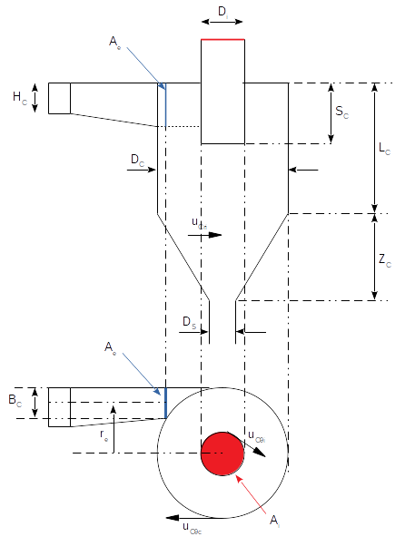
Figure 1 : Cyclone drawing and nomenclature of characteristic geometry
4. Cyclones step by step design guide
How to design cyclones ?
This design guide is based on the works published by Bohnet in 1997. The approach is valid for standard cyclones with squared tangential inlets and with a small dust load in the order of max 10 g/m3. For different types of inlet or higher dust loads, some corrections are necessary.
Validity of the model : as mentioned above it is a good model for estimating the performance of a cyclone in basic design or troubleshooting but gives errors up to 40% vs experiments, depending on the conditions, thus detail calculations should be done with the help of a company specializing in cyclone design and having improved the calculation code.
4.1 Calculate K ratios
If you design a new cyclone, chose one of the standard geometry in table 1 and assume a diameter Dc. If you test an existing cyclone, determine the different ratios for the actual equipment you are evaluating.
K ratios : KH, KB, KS, Ki, KL, KZ, KD from table 1 or actual cyclone dimension
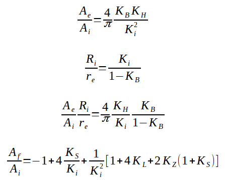
4.2 Calculate the following geometrical dimensions
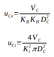
4.3 Calculate inlet and outlet velocities
4.4 Calculate friction coefficients
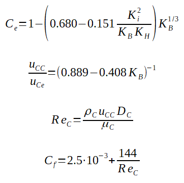
4.5 Calculate the characteristics velocities
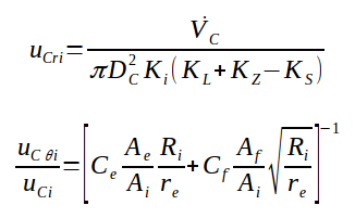
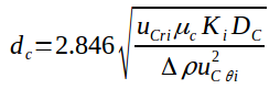
4.6 Calculate the cut off diameter
Particles having a diameter equal to the cut off diameter are captured with an efficiency of 50%. It means that the cyclone will capture 50% of the particles having this diameter in the gas stream and will let through the other 50%.
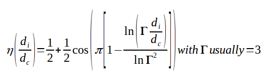
4.7 Calculate the efficiencies
The efficiencies are calculated relatively to the cut off diameter. Bigger particles will lead better efficiencies. Smaller particles to lower efficiencies. A factor Г is used in the calculation and is usually in the order of 3 (+/- 1).
4.8 Calculate the pressure drop

5. Cyclone design Excel calculation & Interactive Tool
Download Cyclone Sizing Excel Spreadsheet
Get the Bohnet design template offline. Customize geometric parameters, calculate cut-off diameters, and generate printable reports. Note that this tool cannot be used for detail design as stated in the file, always link with a commercial company to confirm the design.
Interactive Bohnet Cyclone Sizing Tool
FOR EDUCATIONAL PURPOSE ONLY — NO WARRANTY — ALWAYS CONSULT A REPUTABLE SUPPLIER1. Process Stream Properties
2. Cyclone Configuration
3. Design Calculations
| Inlet Height (Hc): | - m |
| Inlet Width (Bc): | - m |
| Vortex Finder Depth (Sc): | - m |
| Gas Outlet Diameter (Di): | - m |
| Cylinder Height (Lc): | - m |
| Cone Height (Zc): | - m |
4. Performance Outputs
- µm
- Pa
| Inlet Gas Velocity (uCe): | - m/s |
| Outlet Gas Velocity (uCi): | - m/s |
| Wall Boundary Velocity (uCC): | - m/s |
| Cyclone Reynolds Number (Rec): | - |
Frequently Asked Questions (FAQ)
How do you calculate cyclone collector efficiency?
Cyclone collector efficiency is calculated by establishing the grade efficiency function relative to the cut-off diameter (d50). Under the Bohnet model, the efficiency curves are calculated for discrete particle size classes using the ratio of particle diameter to cut-off diameter, mapped against a steepness coefficient (usually Γ = 3). This helps engineers project the total recovery percentage of a specific powder size distribution.
What is the cut-off diameter (d50) in a cyclone separator?
The cut-off diameter, or d50, is the particle size collected by the cyclone separator at exactly 50% efficiency. Particles larger than the d50 are captured with higher efficiency, while smaller particles are progressively lost in the clean air outlet stream. The Bohnet method evaluates this parameters by solving the balance of centrifugal force against drag velocity at the vortex finder boundary.
What are the limitations of the Bohnet cyclone model?
The Bohnet cyclone model is primarily valid for standard cyclones with tangential inlets and low dust loadings (below 10 g/m³). While it offers an excellent mathematical framework for sizing and verification, calculations can vary up to 40% against physical experimental data at high concentrations or alternative inlet geometries. For dense phase process operations, secondary correction factors are required.
Top
5 Most Popular
1.
Pneumatic transport design guide
2. Ribbon
blenders
3. Powder mixing
4. Hoppers design guide
5. Measuring degree of
mixing
--------------

--------------
Top 5 New
1. Continuous Dry Mixing
2. Mixing speed
3. Mixer cycle time
optimization
4. Batch
/ continuous mixing comparison
5. Energy Savings