
Conveying speed / air velocity
Calculations of air velocity in pipes : step by step guide
Recommended values of air velocity in pneumatic conveying pipes
Question or remark ? Please contact us at admin@powderprocess.net
| Section summary |
|---|
| 1. Definition of air velocity in pipe |
| 2. Calculation of air velocity through piping |
| 3. Usual values for dilute phase and lean phase pneumatic transport |
| 4. Air velocity in pipe Excel
calculator |
1. Definition of air velocity in pipe
What is the velocity of air in pipes ?
The conveying air velocity is the speed at which air circulates in the conveying pipe of a pneumatic conveying line. Air velocity is changing all along the conveying line following the pressure / temperature evolution, thus one must always refer to a reference position (beginning or end of the line) when calculating the air velocity. The air velocity is sometimes called conveying air speed.
2. Calculation of air velocity through piping
How do you calculate air velocity in pipes ?
The air velocity in the pipes is calculated by dividing the air volumetric flowrate (m3/s) by the passing section of the pipe (m2).
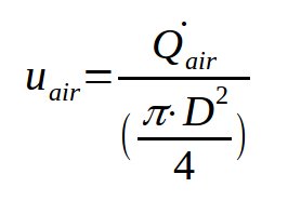
Equation 1 : calculation of the air velocity in a conveying pipe of diameter D
With :
- uair = air velocity in conveying pipe of diameter D (m/s)- Qair = air volumetric flow rate (m3/s)
- D = pipe diameter (m)
Note the following : the air volumetric flowrate is changing with the pressure and temperature, along the conveying line pressure is decreasing thus air expands, which makes the volumetric flowrate higher and thus the conveying air velocity higher (at constant D). To counter this phenomena, it is possible to change the diameter of the pipe, thus D may not be constant all along a same pipe.
Calculator 1: Standard Air Velocity Sizer
CALCULATES PIPING VELOCITY FROM LOCAL/ACTUAL VOLUMETRIC FLOWRATE1. Inputs
2. Sizing Outputs
| Pipe Cross-Sectional Area: | - m² |
| Calculated Air Velocity (uair): | - m/s |
Calculator 2: Air Density & Line Expansion Sizer (Nm³/h)
CALCULATES PIPING VELOCITIES AT INLET/OUTLET BOUNDARIES CORRECTED FROM NORMAL CONDITIONS1. Reference / Normal Conditions
2. Line Boundaries Geometries
3. Beginning of Pipe (Inlet / Pick-up Point)
| Pipe Cross-Section Area: | - m² |
| Actual Air Flow (Qactual): | - m³/h |
| Inlet Air Velocity (uinlet): | - m/s |
4. End of Pipe (Outlet / Terminal Point)
| Pipe Cross-Section Area: | - m² |
| Actual Air Flow (Qactual): | - m³/h |
| Outlet Air Velocity (uoutlet): | - m/s |
How to calculate air velocity in pipe ? Step by step calculation example
A dilute phase conveying system, working by vacuum, is transporting a product from a tipping station to a receiver. The conveying line is powered by a Roots blower sucking 400 Nm3/h of air. Temperature is 20c. The pressure in the receiver is -0.3 bar g. The pipe internal diameter is 80 mm. What is the air velocity at the beginning and the end of the pipe ?
Beginning of pipe
At the beginning of the pipe, the pressure is atmospheric, the temperature is 20c.
STEP 1 : calculate the volumetric air flow at the conditions of the beginning of pipe.
The calculation formula is available here.
Qair = QVN.T/273*1.013/P = 400*293/273*1.013*1.013=429 m3/h=0.119 m3/s
STEP 2 : calculate the air conveying velocity
uair = Qair / (π.D2/4) = 0.119/(π*0.082/4) = 23.7 m/s
End of pipe
At the end of the pipe, the pressure is -0.3 bar g, the temperature is 20c.
STEP 1 : calculate the volumetric air flow at the conditions of the end of pipe.
The calculation formula is available here.
Qair = QVN.T/273*1.013/P =
400*293/273*1.013*(1.013-0.3) = 609 m3/h=0.169 m3/s
STEP 2 : calculate the air conveying velocity
uair = Qair / (π.D2/4) = 0.169/(π*0.082/4) = 33.7 m/s
How to calculate flow rate from air velocity and pipe diameter ?
Equation 1 can also be used when knowing the velocity of air and the pipe diameter. It is then possible to calculate the air flow rate :
Qair = uair * π.D2/4
Again, as air is compressible the air flow will change according to the pressure, and thus according to the position in the pipe.
Top
5 Most Popular
1.
Pneumatic transport design guide
2. Ribbon
blenders
3. Powder mixing
4. Hoppers design guide
5. Measuring degree of
mixing
--------------
Top 5 New
1. Continuous Dry Mixing
2. Mixing speed
3. Mixer cycle time
optimization
4. Batch
/ continuous mixing comparison
5. Energy Savings
3. Usual values of air velocity for dilute and dense phase conveying
What is the typical air velocity in pneumatic conveying ?
Every conveying line is unique and will have its specific air velocity, however, some orders of magnitudes can be given for both dilute and dense phase.
Table 1 : Reference end of line air
velocity for dilute and
dense phase conveying
| Type of conveying | Pressure | Vacuum |
|---|---|---|
| Dilute
phase |
20-25 m/s | 20-30 m/s |
| Dense
phase |
4-8 m/s |
5-10 m/s |
Note that the actual velocity of the product conveyed is lower than the conveying air velocity.
4. Air velocity in pipe Excel calculator
Please access here the Free Excel calculator for air velocity calculation here : calculator download (click here)
Download Air Velocity & Line Expansion Sizing Spreadsheet
Get the professional Air Velocity and Gas Density calculation template offline. Verify line diameters, calculate gas densities, and evaluate system fan volume parameters across different pressure boundaries.
